
CNC probe radius compensation accounts for the separation between a ball-ended stylus's reference position and the physical surface being located. The ball touches the workpiece with its outside surface, not its center. Before interpreting a probing result as an edge, you need to know whether the installed system has already accounted for that separation.
The distinction can hide behind a convincing result. In an ideal two-sided measurement, the midpoint can be correct even when the distance between the contact references is larger than the workpiece. A centered inscription may therefore look right while an individual edge coordinate is wrong. Understanding why helps you distinguish a plausible location from evidence that the complete reference is correct.
The Ball Tip, Its Center, and the Surface
A ball-ended stylus contacts a straight, flat face at the ball's surface. In ideal contact, the shortest line from the ball center to that plane is perpendicular to the plane and has a length equal to the ball radius. The physical face and the ball center are consequently different locations, even at the instant of contact.
Radius and diameter also describe different distances. Diameter runs across the entire ball through its center; radius runs from the center to its surface and is half the diameter. Confusing the two changes the geometric quantity being considered. Neither label, however, tells you by itself which correction an installed probing system uses.
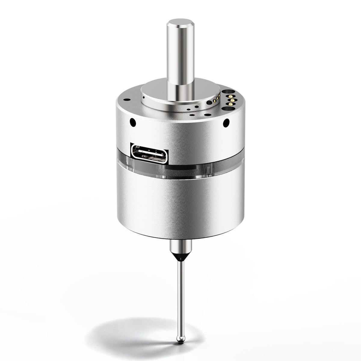
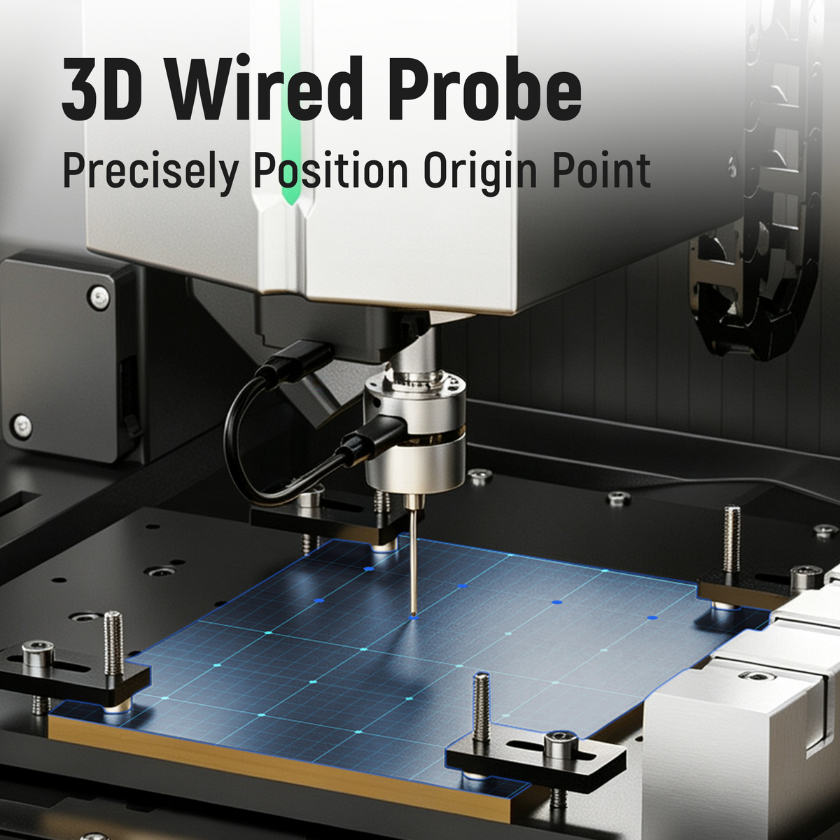
For ED1 users, the TwoTrees ED1 3D wired probe is the dedicated workpiece-origin positioning accessory for the ED1 desktop CNC router. That locating role makes contact geometry relevant to setting a project reference. It is different from assuming that any number shown after a touch is an uncorrected ball-center coordinate.
Two Outside Contacts: A Correct Center but the Wrong Span
Consider a hypothetical block that is exactly 50 mm wide in an illustrative coordinate system. Its straight, parallel outside faces lie at X = 0 and X = 50 mm. Give an ideal spherical stylus a hypothetical radius of 1.5 mm. Assume a centered ball, perpendicular approaches to the two faces and no trigger displacement. These are mathematical assumptions, not ED1 stylus dimensions, machine readings, settings or accuracy results.
At first contact with the left face from outside the block, the ball's center lies to the left of that face. At first contact with the right face from outside, its center lies to the right. The distinction can be kept clear by comparing the physical surface with the ideal center at each contact.
| Contact side | Physical face X | Ideal ball-center X at contact |
|---|---|---|
| Left outside face | 0 | −1.5 |
| Right outside face | 50 | 51.5 |
The span between the ideal centers is 51.5 − (−1.5) = 53 mm. It contains the block's width plus one radius at each end. Treating that span as the block width would therefore include 3 mm that belongs to the two geometric offsets, not to the block.
The midpoint behaves differently: (−1.5 + 51.5) ÷ 2 = 25 mm. That is also the midpoint between the actual faces. One ideal center is displaced left and the other right by equal amounts, so their average remains at the block's center. Subtraction preserves both outward offsets in the span; averaging cancels them at the midpoint.
In this defined coordinate system, recovering the physical left face from its ideal ball center requires moving toward positive X; recovering the right face requires moving toward negative X. Those opposite directions follow from the two outside contacts. They are not universal instructions to add or subtract a radius in a controller, nor do they describe every probing approach.
Imagine a hypothetical design with a centered motif and a second feature located from the left edge. If the motif uses the average of these ideal centers, its center can still land correctly. If the second feature treats the left ball-center coordinate as the physical edge, its reference is displaced. Success with the motif would not validate the second feature's location.
The same limitation remains if a correction leaves equal outward residual errors on both sides: their average can still be correct, while each edge is displaced and the computed width remains too large. Equal inward residual errors would instead make the width too small without necessarily moving that ideal midpoint. This cancellation depends on symmetry. It cannot be assumed for unequal trigger behavior, different contact surfaces or other departures from the model.
Physical Radius Is Not Automatically the Effective Correction
The ideal example ends at first geometric contact. A real probe produces a trigger response, and its system interprets reference information using the applicable calibration and reporting method. That is why a nominal ball dimension is not enough to interpret every real result.
Renishaw's RLP40 installation guide makes a useful distinction: its calibrated radius values relate to the electronic trigger condition rather than simply the ball's physical size. It also treats stylus centering, radius and length as distinct calibration relationships. This illustrates why physical dimensions and effective probing corrections must not be conflated; it does not supply an ED1 calibration procedure or establish that the two products share an implementation.
A radius printed in a stylus specification describes a physical dimension. An effective value used by a particular probing system belongs to that system's defined measurement method. Replacing one with the other merely because both are called a radius can remove a correction the method needs or introduce a correction it has already handled. The applicable machine and probe procedure determines which quantity is relevant.
Find Out What the Result Represents Before Correcting It
A raw reference and a compensated feature coordinate answer different questions. The first relates to what the probing system recorded; the second may already represent the calculated workpiece edge or other feature. A real recorded reference need not equal the ideal ball-center coordinate in the example. A displayed value therefore needs its documented meaning, not a correction inferred from the appearance of the probe.
Return to the hypothetical left face at X = 0. If a result already represents that physical edge correctly, applying an extra positive 1.5 mm shift would move the value to X = 1.5 mm. The additional correction would create an error rather than remove one. The issue is not whether radius compensation is useful; it is whether that compensation has already been included.
This matters when an origin appears misplaced. Shifting the drawing, CAM origin and work offset without first establishing the result's meaning can obscure which relationship was wrong. A geometric explanation is a way to understand the question, not a substitute for the exact installed system's approved setup. Do not import another probe's macros, compensation fields or operating values.
A Chamfer Is Not the Straight Face Beneath It
The simple example assumes that each contact reaches its intended straight side face. Near the top of a chamfered block, the ball might instead touch the sloping chamfer. That contact describes a different surface. Applying the straight-side interpretation to it would not recover the intended edge merely because a response occurred.
For an ideal sphere touching a plane, the center-to-plane separation lies along the surface normal—the direction perpendicular to that plane. On an angled face, that direction is not necessarily the X direction used in the example. A curved transition has its own local contact geometry. An X-only radius shift cannot be treated as a general solution for either situation.
Debris between the stylus and the intended face changes what is contacted, while contact with an unintended face changes which feature is being located. A trigger is a system response, not proof that the intended physical reference has been found. Before any physical setup or inspection, keep the spindle stopped and follow the exact manufacturer's safe isolation, workholding and setup procedures.
A usable edge reference needs agreement between the intended surface, the actual contact geometry and the meaning of the reported result. When those agree under the approved probing method, the correction belongs in that method—not in an extra guessed shift. A convincing midpoint cannot resolve an ambiguous edge, and a response on a chamfer cannot stand in for contact with the straight face the design uses.


