
A flat pattern can look complete on screen and still leave an awkward join when it wraps around a cylinder. For rotary CNC wrap design, the dimension running around the part must correspond to the intended portion of its circumference. The dimension running along the part has a different job. Resizing both without distinguishing them can change the lettering, spacing or proportions you meant to preserve.
For a true reference cylinder, the full-turn span is its circumference: C = π × D, where D is the cylinder diameter. Getting that span right resolves the geometric scale. It does not automatically make the artwork continuous at the join or establish that a particular machine and toolpath can cut it.
The Unrolled Rectangle Has Two Different Directions
Imagine cutting a paper sleeve along its length and laying it flat. One dimension of the resulting rectangle runs along the cylinder's axis. The other runs around its circumference. The paper analogy explains the drawing relationship; it is not a suggestion to attach material to a rotating machining blank.
Do not assume that the horizontal dimension of every drawing is the wrap direction. Vectric's rotary-job documentation explains that, for a job oriented along X, X relates to cylinder length and Y relates to a position around the circumference. For an orientation along Y, those relationships reverse. The important point is to identify which direction the documented workflow wraps, rather than choose a drawing width by visual habit.
The reference diameter also needs a specific meaning. Vectric's cylindrical workflow assumes a perfect cylinder with an exact diameter. Its stock-preparation guidance distinguishes that intended cylinder from an uneven or square starting blank. The largest corner-to-corner dimension of rough stock is a physical-clearance concern; it is not automatically the diameter that should determine the artwork's wrap scale.
Likewise, a carved form with varying radius does not have one universal surface circumference. Establish the reference cylinder required by the particular design and CAM method. Do not substitute the largest decorative ridge, average away a taper or assume that an irregular blank can be represented accurately by one convenient diameter.
Turn the Intended Coverage Into a Drawing Span
Consider a hypothetical decorative band on a cylinder with a 25 mm reference diameter. Its circumference is π × 25, or approximately 78.54 mm. Artwork intended to extend through one full turn uses that circumferential span. A half-turn band uses half the circumference, approximately 39.27 mm. These are mathematical examples, not tested ED1 dimensions, clamping approvals or machining tolerances.
The relationship also works in the other direction. For circumferential artwork length s, the corresponding angular span in degrees is 360 × s ÷ (π × D). This simply expresses the artwork length as a fraction of the full circumference. A quarter of the reference circumference represents a quarter-turn; it is not necessary to distort the drawing until it covers the whole cylinder if the design calls for a partial band.
The axial artwork length remains a separate decision. Making the circumference dimension larger does not require making a name, emblem or border taller along the cylinder. Conversely, scaling the entire drawing proportionally may change that axial dimension when you intended only to adjust the wrap. Decide which physical dimensions matter before applying a general resize command.
Keep enough precision in the design calculation for the intended workflow rather than building a full wrap by repeatedly adding rounded display values. The numbers here are rounded to explain the geometry. For example, six copies of a rounded 13.09 mm value are not mathematically identical to the unrounded circumference divided into six equal parts.
Six Repeats Can Mean Constant Count or Constant Physical Pitch
Suppose the hypothetical band carries six evenly spaced motifs. Each repeat occupies one-sixth of the circumference, approximately 13.09 mm, and one-sixth of a turn, or 60 degrees. This repeat pitch measures the distance from one corresponding point in a motif to the same point in the next. It includes the motif and the intervening space; it is not necessarily the width of the carved shape itself.
Now change the reference diameter to 30 mm while retaining six equally spaced repeats around the full turn. The circumference becomes approximately 94.25 mm, and the pitch becomes approximately 15.71 mm. The angular spacing is still 60 degrees, but the physical distance between corresponding points has increased.
There are several visually different ways to use that extra distance. Keeping each motif's original physical dimensions leaves more space between motifs. Enlarging the motif in the circumferential direction consumes some or all of that space but changes its proportions unless the rest of the design changes deliberately. A narrow symbol or letter may look noticeably wider even though the six-repeat arrangement still closes geometrically.
Keeping the original physical pitch is a different constraint. Using the unrounded pitch from the 25 mm example, the 30 mm cylinder accommodates 7.2 such repeat intervals, not six. A fully repeated band cannot contain a fractional number of identical whole repeats without changing something at the join. The designer must choose another count, adjust the pitch or reserve an intentional gap or partial-wrap region.
The distinction is especially useful for personalized designs. If an emblem's physical width matters, preserve that width and reconsider spacing. If the design's purpose is six equally spaced features, preserve the count and decide how to distribute the new circumference. If a fixed physical repeat pitch matters, accept that a different diameter may not close with the same whole motifs. “Keep the pattern the same” is incomplete until you identify which of those relationships should remain unchanged.
A Full-Turn Span Does Not Design the Join for You
When the rectangle wraps, its two circumferential boundaries meet. A continuous border crossing one boundary must meet the corresponding part of the border at the other. Matching the total span does not move an endpoint to the correct axial position or make two differently shaped edges agree.
Imagine a line that leaves one edge halfway along the decorative band but enters the opposite edge nearer an end. The circumference can be correct while the line still jumps at the join. If the endpoints meet but approach in visibly different directions, the pattern may instead form a corner where you expected a smooth continuation. These are drawing relationships to resolve before using a machining preview as reassurance.
Separated motifs have another kind of join. The gap between the last motif and the first needs to be considered alongside the gaps elsewhere. Leaving a margin at both drawing edges can produce a larger combined gap once those edges meet. That may be an intentional blank region for a different feature, or it may interrupt a rhythm that was meant to be uniform.
A deliberate break is not automatically a design failure. A band can end cleanly on either side of an undecorated region, and a partial wrap can have a defined front. What matters is that the join serves the intended appearance. Adding an arbitrary toolpath overlap or a numerical cutting allowance is not a general solution to artwork whose boundary shapes or spacing do not match.
Connect the Layout to the Actual Rotary Hardware
Once the design has a real circumferential task, the ED1 fourth-axis CNC rotary module kit is the dedicated hardware option to evaluate for the ED1 desktop CNC router. The relevant connection is a supported part that needs rotary presentation. A cylinder-shaped component with a single reachable inscription does not become a full-wrap project merely because rotary hardware is available.
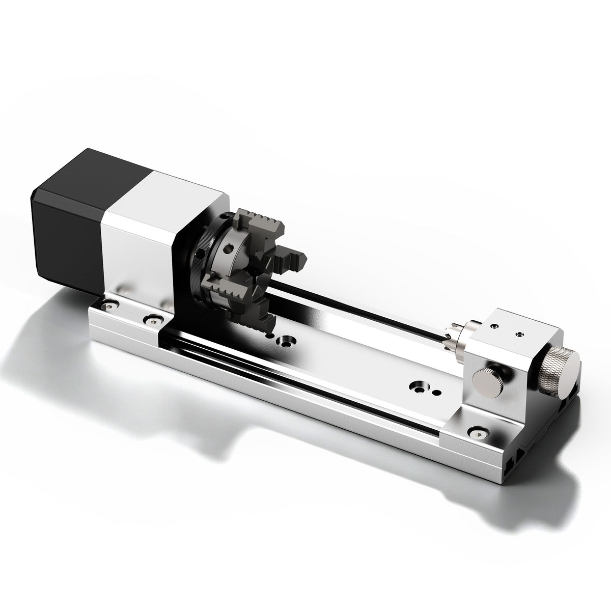
The module's physical dimensions answer a different question from the circumference calculation. They help describe the holding arrangement and available space. They do not specify the reference diameter of every design, establish an artwork's scale or make the full blank length available for decoration. Vectric's stock guidance also notes that holding and clearance from the chuck and tailstock require blank length beyond the design itself.

Software output needs the same separation of roles. Vectric describes wrapping through specially configured post-processors that convert a flat toolpath's X or Y movement into angular movement. That explains its method; it does not establish which Vectric edition, post or controller configuration is suitable for an ED1 project. Use the documented combination for the actual machine rather than infer compatibility from a rotary product image.
A wrapped preview is also a representation rather than an independent measurement. Vectric warns that its visualization can distort some features—for example, round holes can appear oval in the wrapped display. Use a preview to inspect the intended arrangement while retaining the distinction between display geometry and the actual tool, stock and holding setup. Correct drawing dimensions do not resolve omitted hardware or unsafe tool clearance.
For the decorative band, the design decision is complete when the reference cylinder is meaningful, the intended span is defined, the motif count and physical spacing agree, and the join looks intentional. The remaining work is to verify that this design has a suitable documented machining route and secure, accessible holding arrangement. Stop and isolate the machine as its instructions require before hands-on setup; do not adjust artwork registration or stock near moving rotary hardware.


